
I want to share with you about solidworks that explain surface orders. In this cause, I use product view from satelite multimedia as sample to learn how to draw with surface.
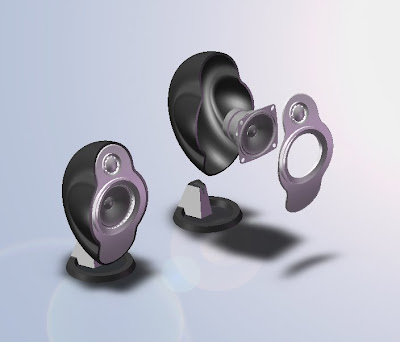

I just take body of satelite as my description below to explain for you step by step to draw it.
First step, create Surface-Revolve
 Second step, create both side surface. In this step, we will create curve surface at both side product. Because the profle like hyperball, so I make it first by create two different sketchs profile. One as a profile and second as path. These steps orders are;


 Third step, because the surface area just half that shown. We need create the complete surface area to close side surface. We need mirror orders to complete this feature, bottom and right side.

 4. Click Mirror on Feature Toolbar to mirror right view
5. Under Mirror/Face Plane select Front Plane and under Bodies to Mirror select Surface-Sweep1 & Mirror1
6. Click OK
4. Click Mirror on Feature Toolbar to mirror right view
5. Under Mirror/Face Plane select Front Plane and under Bodies to Mirror select Surface-Sweep1 & Mirror1
6. Click OK

 Fourth step, trim surface at inner feature. There are sharp edge at Surface Sweep You can delete by use trim surface orders;
 Fifth step, create fillet at edge trim result in 10mm

 Sixth step, surface trim by Arc profile. One of advantage for this progam that is you just create single line sketch that could use as cutting profile


 Seventh step, define thichness surface profile. Because this profile is still in surface area, you can modify to define the thick of profile by use Thicken orders. Just select Insert, Boss/Base, Thichen and under Thicken Parameters you select Profile in Surface To Thicken, then click Thicken Side 2 in Thichness and set 2, so you now get in the thick of product as what do you want. In this exercise set 2.5mm in Thickness. Don’t forget select Merge result.


- Create sketch profile as shown below by click Sketcth on Sketch Toolbar and select Right Plane on Sketch area.
- If you finish create sketch the profile, then click Surface-Revolve on Surface Toolbar. Under Revolve Parameters, select One-Direction in Revolve Type and 360deg in Angle then Line for Axis of Revolution. Click OK.

- Create first sketch by click Sketch on Sketch Toolbar and select Top Plane on FeatureManager. If you finish, click Exit Sketch.
- Then for second sketch click Sketch on Sketch Toolbar and select Right Plane on FeatureManager. Click Exit Sketch.
- Next click Surface Sweep on Surface Toolbar. Under Surface Sweep1 select Sketch2 in Profile and Sketch3 in Path. Click OK.


- Click Mirror on Feature Toolbar
- Under Mirror/Face Plane select Top Plane and under Bodies to Mirror select Surface-Sweep1
- Click OK


- Click Trim Surface on Surface Toolbar or Insert, Surface, Trim
- Under Trim/Type select Mutual. You choice this because on Trimming surface selection, you must select more one surface area or you must all surface area.
- Under Selection select all surface area (Surface Revolve1, Surface Sweep1, Mirror1, and Mirror2[1&2] in Trimming Surface. Select Keep Selection and click in Piece to Keep screen. Then select surface that you want to keep to displayed
- Click OK

- Click Fillet on Fillet Toolbar
- Under Items To Fillet set Radius in 10mm, then select Edge1 & Edge2 in Edges. Click OK


- Click Front Plane on Feature Manager, then click Sketch on Sketch Toolbar. Click Normal To to change at X-Y view
- Create Arc profile by click 3 Point Arc
- If you finish then click Exit Sketch
- Under Selections select Sketch4 in Trim tool, then click Keep selections. In Pieces to Keep select surface area that you keep. Or click Remove Selections then select surface area that want you delete.


1 comment:
hello... hapi blogging... have a nice day! just visiting here....
Post a Comment