 After you cut extrude & circular pattern for helical gear profile, you can use flex & twisting ordered with 15 degree entered angle of helix. That is more simple.

Saturday, July 26, 2008
Use Flex Twisting to Draw Helical Gear
After you cut extrude & circular pattern for helical gear profile, you can use flex & twisting ordered with 15 degree entered angle of helix. That is more simple.
Tuesday, July 15, 2008
Use Cut Swept to Draw Helical Gear
 Cut Swept actually can used for many application, like draw to bolt, nut, helical gear. You just need two step, create sketch the cut profile and make helical path, so you can applicate for many models from these ordered.
Learn More about Helical Gear
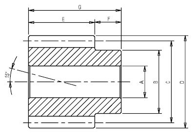
Before to draw helical gear, you must prepare the data of material such as module (m), number of teeth (z), bore diameter (A), hub diameter (B), pitch diameter (C), outside diameter (D), face width (E), hub width (F), total length (G) and angle of helix (α). For detail you can see this illustration:
For more detail helical gear dimension & catalog, please download here!

Direction of helix or angle is 15° can applicate to drawing with search pitch of helical gear. If outside diameter is known, you just find the pitch by the formula :
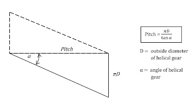
In video tutorial of draw helical gear, the pitch is shown 0.06 revolution. That means is ->(Face Width / Pitch )

If outside diameter (D) = 35.06 mm and angle of Helix = 15° so the Pitch is ( 3.14 x 35.06 ) / tan 15° = 411 mm. And finally the revolution at face width 25 mm is ( 25 / 411 ) x 1 rev = 0.06 revolution.
Friday, July 11, 2008
Mate of Enclosure - Part 2
 You can show how to cut for each edge joining in assembly formatting without you open or work in each part for editing.
Mate of Enclosure - Part 1
 You can see how to assembly of parts by using mate ordered. And at Part 2, I show you how to cut for each edge joining in assembly formatting without you open or work in each part for editing
Saturday, July 5, 2008
How To Draw a Nut
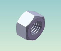 To learn step by step how to draw a Nut M12x1.75 easily. These steps use Extrude, Cut Extrude, Chamfer & Cut Sweep with Helix ordered
LEARN TO DRAW A NUT
Create the Extrusion
To learn step by step how to draw a Nut M12x1.75 easily. These steps use Extrude, Cut Extrude, Chamfer & Cut Sweep with Helix ordered
LEARN TO DRAW A NUT
Create the Extrusion
- Click Extruded Boss/Base
 on the Features toolbar.
The Front, Top, and Right planes appear, and the pointer changes to
on the Features toolbar.
The Front, Top, and Right planes appear, and the pointer changes to  .
.
- Select the Front plane.
- In Toolbar Menu, select Tool, Sketch Entities, Polygon
- Move the pointer to the sketch origin. Click the origin
 , then move the pointer vertically to create a polygon.


 .
.
 on the Sketch toolbar.
 , then move the pointer to create a circle.


 on the Sketch toolbar.


Subscribe to:
Posts (Atom)


