Wednesday, September 26, 2012

Create GROOVE & LIP in pairs Product


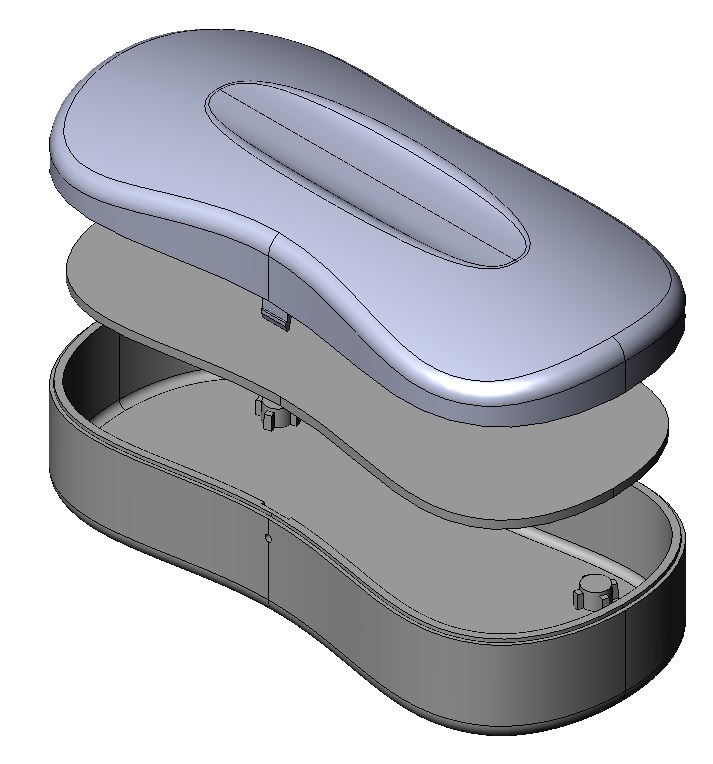
See you again in the  Solidworks Tutorial. Long we did not do an update. Hopefully, all readers can apply the Solidworks program is well. This time I want to raise the topic of how to make the LIP and GROOVE. If you do not know what a lip and groove, let the reader look at this picture about the product of body and cover. The examples of Lip and Groove  can also be found on the  tv remote, mobile phone, telephone, etc.
Well we just started learning. First I would like to specify the products that I make. Call it an energy efficient lighting products that consist of body and glass cover. In the early stages I will make one body and glass cover unity.

1. Revolved BOSS/BASE
  • In the Feature Manager select Front Plane and left click
  • Then point your cursor on the Feature Toolbar and select Revolved Boss / Base or select Insert > Boss / Base > Revolve
  • Create a sketch of the drawing to be as shown below


  • You can use the sketch toolbar menu and select arc and line to create the drawing above.
  • Then put the size or dimension through the sketch toolbar and select smart dimension.

  • For R6 and R40 choose fillet sketch on sketch toolbar
  • Exit Sketch


  • Will appear dialog box Revolve-Thin1.
Under parameter Axis of Revolution, click on the blue line as Axis.
Check the Thin Feature then write T1 with numbers  2.00mm  and click Reverse Direction on Type One Direction under Feature Thin parameters.
  • Click OK
2. SPLIT 
  • Point the cursor on the Feature Manager and click Top Plane.
  • In the Feature toolbar choose Split. Split1 dialog box will appear.
  • Under Trim Tools parameters  the Top Plane that we were going to be clicking automatically became Trimming Surface. Then click Cut Part below.
  • Body will be divided into two that is number 1 and 2. Check one box. Suppose we check the box first, then the Body 1 would change color to magenta.
  • Click OK

3. LIP / GROOVE

Next we will go directly to the discussion topic that makes lip / groove. In order to view lip / groove that we will create later appeared highly visible, we can cut a part into two sections with the Section View command. Choose the Front Plane in the Feature Manager and click on the picture toolbar Section split pipe or View> Display> Section View. So it will look like the drawing below.
  • Then choose Lip / Groove icon on the menu or Insert> Feature Fastening> Lip / Groove, it will display a dialog box LipGroove2-Groove.
  • Under parameter Body / Part Selection choose the body to be made of his groove. In this case select the upper body of conical (Split1 [1])
Then choose the body to be made of his lip. In this case select the lower body that form of a half circle (Split1 [2])
Next, still under parameter Body / Part Selection choose Top Plane in the Feature Manager

  • Furthermore, under the parameter Groove Selection command, there are two options namely "face selection and edge selection". When we had to choose Top Plane as 'planar face' the surface to be our 'groove' will automatically be selected by itself. Now we stay moving box below to select or choose the 'edge' (end / edge) of the areas that are 'groove'. Click on the inner edge. When we did the "Groove Selection", the bottom part will be hidden so that only the upper part only visible part. This is the fun of using SolidWorks.

  • Further! Under Lip Selection parameter which also contained two boxes of selection options, then the surface will be given lip commands will automatically be selected as the Top Plane as its planar face.
Go to selection box below and click, then the upper part turn will be hidden. Now that looks are the lower body. Then click the 'edge' as the inside of the lip area.
  • The final step is to determine the value of groove and lip Parameters that can you see in the picture above at the lower left.
  • Click OK


Don't forget to click the Section View to restore the drawing as a whole. Good luck!

Wednesday, February 29, 2012

Create Conveyor Belt from Sketch of Rolls Assembly

In the design of a conveyor unit that is connected with two or more rolls conveyor, conveyor belt of course we want it attached to his roll. Commands in SolidWorks sketch can help us to create or install his belt conveyor. For the reason in this tutorial, I will be indicating to you how to create a 'New Part' Conveyor Belt on an assembly drawing, so if you would edit a diameter of rolls or adjust the position of rolls, so the conveyor belt will automatically editted. As ilustration, below is an example of drawing which is mounted conveyor belt unit, which at the time of drawing it with the command Insert> Component> New Part.


And below is a drawing of the conveyor unit is not installed belt conveyors.
 

Some steps to create a conveyor belt:
1.    Hide all parts except the rolls
  • Invert Selection. Selection of all rolls (don’t forget to press 'Ctrl' on the keyboard) and then right click and choose Invert Selection.
 

  • Hide Invert Selection. The above command will select all the parts in except the rolls. Then at the drawing view, right click and select hide. Then all the selected part will be hidden and visible only the rolls.

         So it will look like this.


2.    Creating a new Part in an Assembly
  • Insert New Part. Choose Insert> Component> New Part. The show will appear at the bottom-left of the screen "Select the face or plane on which to position the new part". Then point the cursor on the Front Plane in the Feature Manager, left click. Well, now you are ready to make a sketch of the new part.
  • Convert Entities. Choose ‘Normal To’ or press 'Ctrl + 8' to display planar face of his suit. Choose one of the roll and then click edge circle of roll. Click Convert Entities on the Feature toolbar. Dialog box Convert Entities will appear. Continue by selecting all edge of rolls. Finish by clicking OK.
  • Open Part. Make it easier for the process of making a sketch, I suggest you to open a new part. Click part1 on the Feature Manager and selection box will appear. Choose Open Part. And now you're ready to make a sketch of the conveyor at a new part.


3.    Creating a profile sketch on new part
  • Edit Sket. Now the new part has been opened and you are ready to make a sketch on the new part. In the Feature Manager select Sketch1 then click Edit on the sketch dialog box that appears.
  • Normal To. Choose Normal To (Ctrl +8) on the View Orientation for view corresponding of his face planar.
  • Offset Convert Entities. We assume that the thick conveyor is 2mm, the edge of roll has been converted need to be offset in advance as far as 2mm. Meant that the entire surface of the conveyor will offend roll surface. The illustrations are as shown below. Choose the Offset Entities on the Sketch toolbar. In the dialog box enter the distance of 2mm and check the 'Make base construction'.
  

  • Line. Connect the circles with one circle to another by selecting the Line Sketch toolbar. Considering this is a meeting between the lines with circles, then before you specify the start position and end position, first click on the Quick Snap Tangent Snaps toolbar or choose Tools> Relations> Quick Snaps > Tangent.

  • Then point the cursor at the first circle tangent sign to appear, and then left click. Continue by connecting to the next until the circle is also tangent sign before you left click. And to connect back to the next circle, left click twice and then repeat the above steps.
 

                                To form a groove like this.


  • Trim Entities. Use this command to delete the profile sketch that didn’t pass through the conveyor. In the dialog box choose the 'Trim to closest' then click the deleted entity. Exit Sketch.


4.    Belt Forming. This is the final command to create the look his belt conveyor.
  • Extruded Surface. Profile that we created then we extrudes by selecting Extrude Surface command on Surface toolbar (previously we first click Sketch profile on the Feature Manager). In the dialog box that appears under parameter Direction 1, write the width of 1200mm and the End condition set in the Mid Plane. Click OK.
 

  • Thicken. Create a solid feature by selecting one or more surfaces. On the Surface toolbar choose Thicken. Then in the dialog box select the surface and write the thickness at 2 mm and click Thicken Side 1. OK. The blue color is essentially a surface. Give the color with Edit Appearance command on View (Heads-Up) toolbar.


  • Save As. Give name of the Conveyor Belt and close the file. Drawing Assembly will automatically rebuild itself.


Support Us

Technology Blogs TopOfBlogs Technology blogs BRDTracker Technology Blogs - Blog Rankings Active Search Results
hostgator coupon code