Thursday, November 12, 2009

Extruded Cut versus Revolved Cut

Previously I had problems when making the command of chamfer at edge bolt heads, which form of bolt head, is hexagonal. In the Toolbox provided by Solidworks, you'll see that the commands used to create a chamfer on the head bolts using Revolved Cut, where you need to make a sketch as cutter.

Here are the details;

Use Revolved Cut; 1. Choose Insert > Cut > Revolved, then create line Sketch at Front Plane

2. Exit Sketch 3. Under Revolve Parameters a. Select horizontal construction line at center of bolt as Axis of Revolution b. Revolved Type at One-Direction c. Set Angle at 360 degree 4. Click OK

Use Extruded Cut; 1. Choose Insert > Cut > Extruded, then create circle sketch at Front Plane

2. Exit Sketch 3. Under Direction 1 a. Set End condition at Through All b. Check Flip side to cut c. Set Draft Angle at 60 degree 4. Click OK And the final picture is So you want to choose which way?

Friday, November 6, 2009

Line Sketch as Cut Extrude Command

I would say that a line (single profile when in the mechanical desktop) can be used as a profile to cut a model. In this tutorial, I show examples of Spring Collet model where the end result after using the sketch lines cut will look like the picture below

The steps are as follows; 1. Create a Spring Collet part as shown image below. Then create a sketch with the command line and choose Tools> Sketch Entities> Line, and then click a plane on the surface of the Spring Collet 2. Change the view by selecting view at Normal to 3. Create a vertical line in the middle of the circle's outer Collet, then exit sketch

4. Change the display to isometric, and choose Insert> Cut> Extrude. Before this command chose, make sure the sketch line you first click. 5. Then the screen will display images like this,

6. Don’t panic. On FeatureManager design tree dialog box will appear as shown in the picture above, and then setting the option; a. Non-active the box of Direction 2 b. Activate the box of Thin Feature c. Change Type to Mid Plane d. Set Distance to 1.50mm e. Under Direction 1, change End Condition from Through to Blind f. Then set Depth to 55mm So it will look like the following picture. Then click OK

7. Next use the circular pattern to make the same cut as the above command. But first created the axis line with the command Insert> Reference Geometry> Axis and then click on cylindrical/conical face. Click OK 8. For circular pattern command, choose Insert > Pattern/Mirror > Circular Pattern. On FeatureManager design tree, under Parameter; a. Choose Axis1 as Pattern Axis b. Check the boxes Equal spacing c. Set Number of Instance to 3 Under Features to Pattern, select Cut-Extrude-Thin1. Click OK

9. With the steps and the same command, make cut extrude for the lower surface of spring Collet spring in the middle between the upper Extrude cut.

Thursday, November 5, 2009

Cut Extrude with Direction of Extrusion

If you want to make the Cut Extrude command to the slope as the example picture above, the steps are;
  1. Create a sketch like the image below for cutter tool
  2. Choose Insert > Cut > Extrude
  3. On Feature Manager under Direction 1, set End Condition at Through All and at Direction of Extrusion, select edge of part
  4. Then exit sketch

Wednesday, August 26, 2009

Draw Spring with Both Side Surface are Flat

Some time ago, I received a message from a visitor who asked about how to make a spring, where the both side surface are flat. This spring model I have ever seen on injection mold applications. This time I will try to make the picture by using helix / spiral command with variable pitch parameter choices.

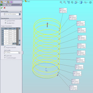
The first step is to create a sketch a circle with diameter of 60, and choose Insert > Curve > Helix/Spiral. Will appear Helix/Spiral dialog box, and under Parameter select Variable Pitch. Then fill the region parameters such as the example image below. For Rev 0, 1, 10 & 11 write Dia = 60mm and P = 5.2mm. Then Rev 2 until 9 write Dia = 60mm and P = 13.5mm. Don't forget to select his Start angle at 90 ° (but this is only option, for this tutorial please follow) and select Clockwise.

The next step, make a rectangle sketch like the example below on the front-plane. Click EXIT SKETCH.

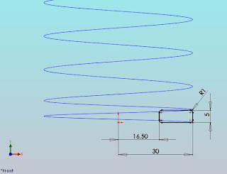
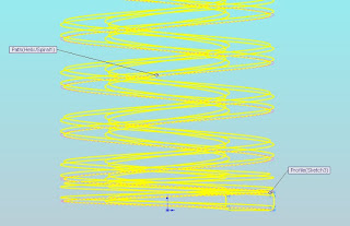
Now we have made a sketch of rectangle that will be used as a profile of a spring. You can also change the profile above by another spring profile as you wish. Then to display the 3D profile, choose Insert > Boss/Base> Sweep. Under Profile and Path, select sketch in the Profile box and select Helix in the Path box. Choose OK.

In order for the bottom surface of the spring and the upper are flat, use the cut extrude command. For spring bottom, make sketch with the circle diameter is 70 on Top Plane, then use the cut extrude command by choose Insert > Cut > Extrude. Under the Direction box, choose Blind and write Depth is 2.5mm with the arrows to the top or towards the spring extruded. Whereas for the upper spring, make circle sketch again with diameter is 70 on the Top Plane, then use cut extrude command by choosing Insert > Cut > Extrude. Under Form box, choose Vertex. Then in the Select A Vertex box, click the outer edge of the spring is shown with a green dot. Under Direction, choose Blind and write 2.5mm in depth with direction arrows is down at the spring extruded.

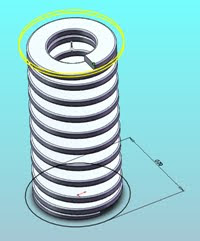
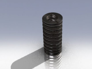
If all the above steps correctly, God willing springs image will look like below. Good luck!

Tuesday, May 12, 2009

Create Body Satelite By Surface Command

I want to share with you about solidworks that explain surface orders. In this cause, I use product view from satelite multimedia as sample to learn how to draw with surface.
I just take body of satelite as my description below to explain for you step by step to draw it. First step, create Surface-Revolve
  1. Create sketch profile as shown below by click Sketcth on Sketch Toolbar and select Right Plane on Sketch area.
  2. If you finish create sketch the profile, then click Surface-Revolve on Surface Toolbar. Under Revolve Parameters, select One-Direction in Revolve Type and 360deg in Angle then Line for Axis of Revolution. Click OK.
Second step, create both side surface. In this step, we will create curve surface at both side product. Because the profle like hyperball, so I make it first by create two different sketchs profile. One as a profile and second as path. These steps orders are;
  1. Create first sketch by click Sketch on Sketch Toolbar and select Top Plane on FeatureManager. If you finish, click Exit Sketch.
  2. Then for second sketch click Sketch on Sketch Toolbar and select Right Plane on FeatureManager. Click Exit Sketch.
  3. Next click Surface Sweep on Surface Toolbar. Under Surface Sweep1 select Sketch2 in Profile and Sketch3 in Path. Click OK.
Third step, because the surface area just half that shown. We need create the complete surface area to close side surface. We need mirror orders to complete this feature, bottom and right side.
  1. Click Mirror on Feature Toolbar
  2. Under Mirror/Face Plane select Top Plane and under Bodies to Mirror select Surface-Sweep1
  3. Click OK
4. Click Mirror on Feature Toolbar to mirror right view 5. Under Mirror/Face Plane select Front Plane and under Bodies to Mirror select Surface-Sweep1 & Mirror1 6. Click OK
Fourth step, trim surface at inner feature. There are sharp edge at Surface Sweep You can delete by use trim surface orders;
  1. Click Trim Surface on Surface Toolbar or Insert, Surface, Trim
  2. Under Trim/Type select Mutual. You choice this because on Trimming surface selection, you must select more one surface area or you must all surface area.
  3. Under Selection select all surface area (Surface Revolve1, Surface Sweep1, Mirror1, and Mirror2[1&2] in Trimming Surface. Select Keep Selection and click in Piece to Keep screen. Then select surface that you want to keep to displayed
  4. Click OK
Fifth step, create fillet at edge trim result in 10mm
  1. Click Fillet on Fillet Toolbar
  2. Under Items To Fillet set Radius in 10mm, then select Edge1 & Edge2 in Edges. Click OK
Sixth step, surface trim by Arc profile. One of advantage for this progam that is you just create single line sketch that could use as cutting profile
  1. Click Front Plane on Feature Manager, then click Sketch on Sketch Toolbar. Click Normal To to change at X-Y view
  2. Create Arc profile by click 3 Point Arc
  3. If you finish then click Exit Sketch
  4. Under Selections select Sketch4 in Trim tool, then click Keep selections. In Pieces to Keep select surface area that you keep. Or click Remove Selections then select surface area that want you delete.
Seventh step, define thichness surface profile. Because this profile is still in surface area, you can modify to define the thick of profile by use Thicken orders. Just select Insert, Boss/Base, Thichen and under Thicken Parameters you select Profile in Surface To Thicken, then click Thicken Side 2 in Thichness and set 2, so you now get in the thick of product as what do you want. In this exercise set 2.5mm in Thickness. Don’t forget select Merge result.

Wednesday, May 6, 2009

Combine Bodies

mbine Bodies

From Solidworks Help Topics. You can combine multiple solid bodies to create a singled-bodied part or another multibody part. There are three ways to combine multiple solid bodies:

Combine Bodies

To use the Add or Common operation type:

Combine Bodies

  1. Click Combine on the Features toolbar, or click Insert, Features, Combine.

    The Combine1 PropertyManager appears.

  2. Under Operation Type, click Add or Common.

  3. Under Bodies to Combine, select the bodies in the graphics area, or select the bodies from the Solid Bodies folder in the FeatureManager design tree.

  4. Click Show Preview to preview the feature.

  5. Click OK .Combine Bodies

    Combine Bodies<p<p<p<p<p<p<p<p<p<p

    Combine Bodies

    • Add. Combines solids of all selected bodies to create a single body.

    Combine Bodies

    • Common. Removes all material except that which overlaps.

    To use the Subtraction operation type:

    1. Click Combine on the Features toolbar, or click Insert, Features, Combine.

      The Combine1 PropertyManager appears.

    2. Under Operation Type, click Subtract.

    3. Under Main Body, select the body to keep from the graphics area for Solid Body , or select the body from the Solid Bodies folder in the FeatureManager design tree.

    4. Under Bodies to Subtract, select the bodies whose material you want to remove for Solid Bodies .

    5. Click Show Preview to preview the feature.

    6. Click OK .

    Combine Bodies

    • Subtract. Removes overlapping material from a selected main body.

Tuesday, May 5, 2009

Edit Radius from import Part by Delete and Patch ordered

Deletes a face from a surface body or solid body and automatically patches and trims the body. To delete and patch faces on a surface body: 1. Click Delete Face on the Surfaces toolbar, or Insert, Face, Delete. The Delete Face PropertyManager appears. 2. In the graphics area, click the faces you want to delete. The names of the faces appear under Faces to delete . 3. Under Options, click Delete and Patch. 4. Click OK . The faces disappear, and the adjoining faces extend to form an unbroken surface. Select green faces to delete Gray faces patched 5. Click Fillet on the Surface toolbar, or Insert, Feature, Fillet/Round. 6. The Fillet PropertyManager appears. In the graphics area, click the edges you want to fillet. The names of the edges appear under Edges . 7. Under Items To Fillet, set Radius in 0.2mm. 8. Click OK.

Support Us

Technology Blogs TopOfBlogs Technology blogs BRDTracker Technology Blogs - Blog Rankings Active Search Results
hostgator coupon code