 2. Change the view by selecting view at Normal to
3. Create a vertical line in the middle of the circle's outer Collet, then exit sketch
4. Change the display to isometric, and choose Insert> Cut> Extrude. Before this command chose, make sure the sketch line you first click.
5. Then the screen will display images like this,
6. Don’t panic. On FeatureManager design tree dialog box will appear as shown in the picture above, and then setting the option;
a. Non-active the box of Direction 2
b. Activate the box of Thin Feature
c. Change Type to Mid Plane
d. Set Distance to 1.50mm
e. Under Direction 1, change End Condition from Through to Blind
f. Then set Depth to 55mm
So it will look like the following picture. Then click OK
7. Next use the circular pattern to make the same cut as the above command. But first created the axis line with the command Insert> Reference Geometry> Axis and then click on cylindrical/conical face. Click OK
8. For circular pattern command, choose Insert > Pattern/Mirror > Circular Pattern. On FeatureManager design tree, under Parameter;
a. Choose Axis1 as Pattern Axis
b. Check the boxes Equal spacing
c. Set Number of Instance to 3
Under Features to Pattern, select Cut-Extrude-Thin1. Click OK
9. With the steps and the same command, make cut extrude for the lower surface of spring Collet spring in the middle between the upper Extrude cut.
Friday, November 6, 2009
Line Sketch as Cut Extrude Command
I would say that a line (single profile when in the mechanical desktop) can be used as a profile to cut a model.
In this tutorial, I show examples of Spring Collet model where the end result after using the sketch lines cut will look like the picture below
The steps are as follows;
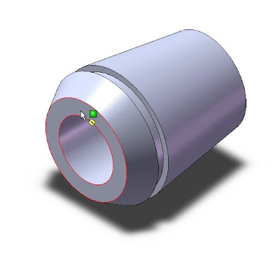
1. Create a Spring Collet part as shown image below. Then create a sketch with the command line and choose Tools> Sketch Entities> Line, and then click a plane on the surface of the Spring Collet
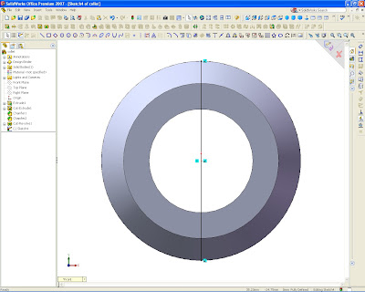
 2. Change the view by selecting view at Normal to
3. Create a vertical line in the middle of the circle's outer Collet, then exit sketch
4. Change the display to isometric, and choose Insert> Cut> Extrude. Before this command chose, make sure the sketch line you first click.
5. Then the screen will display images like this,
6. Don’t panic. On FeatureManager design tree dialog box will appear as shown in the picture above, and then setting the option;
a. Non-active the box of Direction 2
b. Activate the box of Thin Feature
c. Change Type to Mid Plane
d. Set Distance to 1.50mm
e. Under Direction 1, change End Condition from Through to Blind
f. Then set Depth to 55mm
So it will look like the following picture. Then click OK
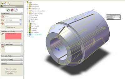
7. Next use the circular pattern to make the same cut as the above command. But first created the axis line with the command Insert> Reference Geometry> Axis and then click on cylindrical/conical face. Click OK
8. For circular pattern command, choose Insert > Pattern/Mirror > Circular Pattern. On FeatureManager design tree, under Parameter;
a. Choose Axis1 as Pattern Axis
b. Check the boxes Equal spacing
c. Set Number of Instance to 3
Under Features to Pattern, select Cut-Extrude-Thin1. Click OK
9. With the steps and the same command, make cut extrude for the lower surface of spring Collet spring in the middle between the upper Extrude cut.
Subscribe to:
Post Comments (Atom)


No comments:
Post a Comment