Monday, November 14, 2011

How To Draw a Nut in a Fully Define Sketch

“Nut”border=
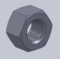
In a previous post, I have made a model of how to draw a Nut. This time I will make another model with some improvements, the most prominent of which is to make a sketch to fully define sketch. This can be easily sketch the outline color from blue to black. Also other improvements such as traffic command without first having to click OK in the dialog box to continue with the next command. In addition to saving command also saves time making the picture. But that does not mean Nut model that I made this the most perfect, that you should emulate. No. You can improvise with other commands that may be different from what I do, but it gives the same result. Well, I just started making steps:

1. Extrude Boss, to create the body
  • Right Plane. Right click on Plane and then click Extruded Boss on the Feature Toolbar
  • Sketch of Polygon. Sketch toolbar is automatically active. Select Polygon and then place the cursor on the Origin view, slide to the right slightly and then click OK. Number of sides will automatically be pointed to figures 6 (six)
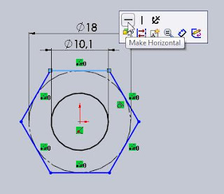
  • Smart Dimension. Click on the Sketch toolbar smart dimension and set it on a 18mm diameter circle.
  • Sketches a Circle. Make a circle by selecting the Circle on the sketch toolbar. Place a circle right in the middle of sketch polygons. This circle is in a hole the size of the nut. Determine the size of the diameter at 10.1mm by choosing smart dimension sketch and then click the circle.
  • Add relations. In the sketch toolbar select add relations and then click one horizontal line on sketch of polygon. In this tutorial I took the upper horizontal line. You can see the difference in horizontal lines that I have now changed click color from blue to light blue. Then a small box will appear at the top right and select the make horizontal. This command will make the sketch changed to fully define sketch in which the color changed from blue to black. Exit Sketch.
       
  • Depth. In the Dialog Box Boss-Extrude write with 10.8mm thickness. Then in select Mid Plane End condition. Click on OK.
 

2.  Extruded Cut, to makecreate a chamfer on both sides of the nut
  • Sketches by a circle. Click on the front surface of the nut and then select Feature Extruded Cut on the toolbar. Sketch toolbar is now active. Select the Circle on the Sketch toolbar and then on the Origin and end up outside the circle touching the sides of the polygon.
    

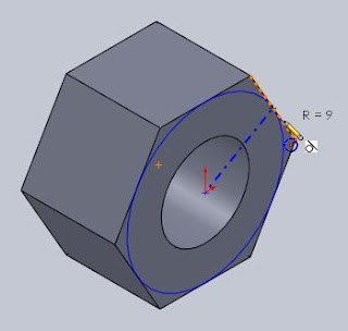
  • Add relations. Then you just choose Add Relation to sketch the toolbar without having to click OK on the dialog box circle. In the Add Relation dialog box will be automatically selected under parameter Arc1 Selected Entities. Now you just need to click on one of the outer edge of the polygon are tangent to the line of the circle.
  • Tangent. Click below the parameter tangent Add Relations. Click on OK. Continue to Exit sketch. (If you want to see if the circle has changed color to black, left-click on any image area outside the image model).
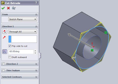
  • Draft Angle. Dialog box will appear. Then fill in the End condition under Direction1 parameters on Through All. Click the Flip side to cut. Draft On and set at 60 degrees. Click on OK.
 

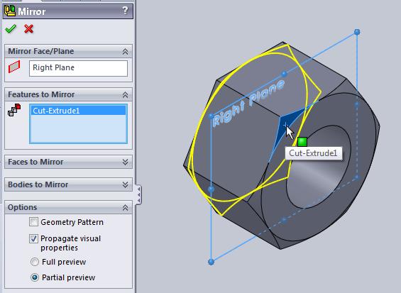
3. Mirror, create a copy of the extruded cut command to chamfer the back side
  • Right Plane. Right click on Plane Mirror Feature and then click Toolbar.
  • Feature to mirror. Selection of features that have been truncated. Then click OK.

4. Chamfer, adding the chamfer command on both sides of the hole inside.
Select the chamfer on the Feature toolbar. Then on the chamfer parameters, selection of the two sides will chamfered. Set on a 1mm distance. Click on OK.


5. Swept Cut, creating a threaded groove

  • Helix and Spiral. Selection of one surface of the Nut. Select the Helix and Spiral on Feature toolbar. Selection the outside of the circle that chamfered and then select Convert Entities on the Sketch toolbar. Click OK. 
  • Pitch. In the dialog box that appears, under the parameters of Defined By, select Height and Pitch. Set the Height to 12mm (or thicker than thick of Nut) and Pitch at 1.75mm. Click the Reverse direction and set the Start angle at 0 degrees. Click OK.
 
  • Sketches by a polygon. In the Feature Manager select the Top Plane and select the Polygon on the Sketch toolbar that automatically activated. On the View Orientation select Normal To (or press Ctrl +8).
  • Number of sides. Set the number of sides on 3 in the dialog box. Select the Smart Dimension and set distance above the end point of the triangle with the origin at 6mm and set the width of the base triangle at 1.5mm or smaller than 1.75mm of pitch.
  • Add relations. Select the Add Relation to sketch the toolbar and create relationships like the picture below that is the leftmost point coincident with the edge of the nut and the base triangle is made horizontal. Exit sketch.
  • Swept Cut. Directly select Swept Feature Cut on the toolbar. In the profiles dialog box will be selected automatically. And now you live below the Path selection profile parameters. Click OK.

The results of the model will be like the picture below
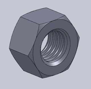


GOOD TRY!


Wednesday, October 19, 2011

Tips & Tricks

SOME USEFUL TIPS WHILE WORKING WITH SOLIDWORKS
1. Try using the 3 default planes as max as possible.
2. Select the proper plane to begin your sketch.
3. Use mouse right click option to select the commands in ease manner, like select from the drop down menu or from recent commands.
4. Always use a fully defined sketch.
5. Make a customized toolbar to use the feature and other options.
6. Use mouse buttons for zoom in/out, rotating and panning the models.
7. Click off the things in the “View” like temporary axes, sketch relations, etc.
8. Keep level of details on lower side and mate animation speed set to fast in Tools>Option>System Option> Performance.
9. Keep Image quality in Tools>Option>Document properties on lower side.
10. Don’t change the default settings for line types, colors, etc.
11. Use design table/ Configurations in parts & assembly.
12. Use equations/ link values to work quicker.
13. Make default templates for metric/ inches settings for part, drawing & assembly.
14. During applying mates in assembly, select the edge, press “Alt” button and drag the part to respective face to get the concentric and coincident mate in one go.
15. Press “Alt” while reordering parts in the main/top level assembly to avoid them being added to the any sub assembly.
16. Use faces, axes, default planes for mating in assembly.
17. Use design library to create parts/features to be used repeatedly.
18. While making and default plane or axis try using default planes as reference.
19. Turn off the SW Thumbnails
20. To show “Cosmetric Thread”, choose Tools>Option>document Properties>Detailing>Shaded cosmetic thread
21. Drag a box around items to select.
22. RMB selection options:   Select loops, chains, tangency, partial loops, open loops, Select Midpoint,etc.
23. Don’t rename files from Windows Explorer unless it is a document with no references (part not used in an assembly, assembly not used in another assembly or a drawing), or you know in advance how you’re going to solve the problem which you’re about to create.
24. Use menu File, Save As when the assembly is open to attach renamed file to existing assembly.
25. Use SolidWorks Explorer to copy or rename files and maintain references
26. File naming conventions
* Avoid names like “bracket”, “cover”, “base”, etc.
*SolidWorks can only have one part with a given name open at a time
* The second part with the same name as another open part will use the first opened part
* It is best practice to use sequential part numbers in such a way that you can guarantee that there will not be any duplicate file names.

SHORTCUT KEYS
1.    F = Zoom to Fit
2.    Ctrl+Shift+Z  = Previous View
3.    Ctrl+1 = Front View
4.    Ctrl+2 = Back View
5.    Ctrl +3 =Left View
6.    Ctrl +4 = Right Vie w
7.    Ctrl +5 = Top View
8.    Ctrl +6 = Bottom View
9.    Ctrl +7 = Isometric View
10.    Ctrl +8 = Normal To View
11.    Ctrl +B  = Rebuild
12.    Ctrl-TAB =  Cycles through open SW documents, Also works in other Windows applications.
13.    Alt+TAB =  Cycles through open applications.
14.    Arrow = rotate 15 degrees (settable in Tools, Options)
15.    Shift+Arrow = rotate 90 degrees
16.    Ctrl+Arrow = pan
17.    Alt+Arrow = spin around screen center
18.    Move dims / Copy dims: Move = Shift-drag, Copy = Ctrl-drag


OTHER THINGS TO BE TAKEN CARE OFF
1. Defragmentation and disk cleanup once in 15 days
2. Remove Temporary Files from:
C:\temp, C:\\temp, \Local Settings\temp, swxXXX folders, Swxauto folder (SW Auto Recovery Files).
3. Remove Temporary Internet Files from \Local Settings\Temporary internet Files.

General Windows Tricks
How to Take a Screenshot
1)   Press the “Print Screen” button. The button is located on the right top corner of the keyboard.


2)   Open Microsoft Paint. To do this, click Start > All Programs > Accessories > Paint. Click inside the white part of the screen. Alternatively you can open a new word file.
 

3)   Go to the Edit menu and click Paste or you can press and hold “Ctrl” and press V
4)   Click File > Save As. In the box that pops up, change the “Save As Type” to PNG or JPG. Type in a filename for your image. Choose a place to save, like the Desktop and click on save.
5)   If you are using a word file, then continue pasting in the next page if you want to take more than one screen shot and save in same file. And finally save your file.

Source: http://gupta9665.wordpress.com/tips-tricks/  with some additional.

Thursday, October 6, 2011

Create Hole Wizard with Polygon Sketch at Flange Model

How have you been getting accustomed to using Solidworks? I hope so. In this paper I want to show you about the Hole Wizard command. You can create these types of Hole Wizard holes:
  •  Counterbore
  •  Countersink
  •  Hole
  •  Straight Tap
  •  Tapered Tap
  •  Legacy

For placement Hole Wizard, this time I use help command of Polygon Sketch. Where you first create a sketch of a polygon, then the corner points of this polygon you just put the lock position. Also look at the hole cosmetric thread to be created by adding setting the Tools, Options, Document Properties, Detailing, shaded cosmetic threaded.

I will create a simple example of the Hole Wizard command on an image Flange. There are three cosmetic threaded holes in the image above.

Here are the steps:

1. Creating Revolved Sketch
Featured on the toolbar, select Revolved Boss and select the Front Plane. Sketch toolbar is now active. Create a profile sketch of a line to form a flange. Determine the dimensions like the example image below. Also add "Centerline" horizontally on the "Origin" as the "Axis of Revolution". Click OK.
2. Revolved Boss
To end the command create a profile sketch above click Exit Sketch. In the dialog box under Revolve Parameters will automatically make the "Centerline" as the "Axis of Revolution". Finish by clicking OK.
3. Polygon Sketch
Next is to create a sketch polygons as lines of dots at the same time help the "Hole Wizard" that we will create later. In the "Sketch toolbar"  select "Sketch" and select "a planar face". On the Sketch toolbar select Polygon. Change "View Orientation" on the Right or press (Ctrl + 4).

In the dialog box, type "Number of Side" at number 3 or can also click the down arrow button until the numbers changed from 6 to 3. Select the "circumscribed circle". Then place the cursor on the origin, left click and drag the cursor over approximately close to the line outside the flange and left click again.

Back to the dialog box, click "For construction" under the parameter "Option". Finish by clicking OK.


4. Smart Dimension and Fully Define Sketch
Then the set of "Pitch Circle Diameter (PCD)" on 100mm by selecting the "Smart Dimension" in "Sketch" toolbar. This command to its diameter to be "fully define sketch". Click OK.

Next in order triangles are also to be "fully define sketch", click the triangle base is horizontal and then a small dialog box will appear to the right of the cursor, click the "Make Horizontal". Finish by clicking OK.


5. Hole Wizard
Before concluding this flange model image by making "Hole Wizard", set the first appearance of thread holes into "cosmetic threaded". Select Tools, Options, Document Properties, Detailing, shaded cosmetic threaded.
 
Next on the "Feature toolbar"  select "Hole Wizard". Dialog box will appear. There are two tabs, namely Type and Positions.
 
On the Type tab;
  • Under Type, select Straight Tap Hole, Standard: Ansi Metric, and Type: bottoming Tapped Hole.
  • Under Hole Specifications select  Hole Size: M10X1.5.
  • Under End Condition select Through All .
  • Under Options select Cosmetic thread.
On the tab Positions, click 3D Sketch then click the sketch ends of the triangles as the "Hole Wizard". Finish by clicking OK.

Good to here how to draw the following flange adds "Hole Wizard" using the help of my finished sketch polygons show the sequence. Good try!


Sunday, September 25, 2011

Create a Handle by Offsetting a Sketch from the Front Planar

Dipper of water that I often wear when bathing is very interesting for model made its 3D image. There are two parts that can be aggregated before we start drawing, the water container and the handle. Although simple but it never hurts for us to try to create an image model. Dipper model that you encounter may be different than what I got. But one thing is not different is the top cross-sectional area larger than the bottom section. There is no intention other than to facilitate the model problem also print or injection process.


Immediately, we begin to draw


On the menu select File, New. Part and then click OK.

On Feature toolbar or select Insert Extruded Boss, Featured, Extruded Boss/Base. Then determine its plane by selecting the top plane. Make a sketch of a circle with a diameter of 150mm (we could write a diameter of 150 in the dialog box or we can also use smart sketch dimension on the menu). Click Exit the sketch. Then in the dialog box below Direction1 select End Condition: Blind to the direction of the arrow upwards. Set Depth to 100mm, angle of 2 degrees, the check draft outward. Then click OK.

Then with the same command, select the Extrude Boss. Then place the cursor on the upper surface of the Extrude Boss that we just created to determine the location of his plane. Click the upper-outer edge of the Extrude Boss was then select Convert Entities on the Sketch menu. Then we will have a sketch of a circle that has been "fully define sketch" whose characteristics we can see that the circle is black instead of blue, without having to make a sketch first and enter the circle diameter value. Then in the dialog box below Direction1 select End Condition: Blind to the direction of the arrow upwards. Set Depth to 40mm, angle 10 degrees, check draft outward. Then click OK.


Next we add the radius of 7mm at the bottom outer edge of the image above. On Feature toolbar or select Insert Fillet, Feature, Fillet.


Thick dipper on this model I created with a thickness of 2mm. To make it from a solid to above select command shell on the toolbar or Insert Feature, Feature, Shell. Click the surface in which you want holes are marked in blue. Check the preview show to see the picture of the results we will get later. Click OK.


-->
Rotate the image to see the profile of the bottom by clicking the scroll, hold, then move the mouse until the bottom looks. This time we will add the rib at the base of dipper that serves as an amplifier as well as foot bailer. On the toolbar select the Extrude Feature and click on the bottom surface so that changes color to blue, which is as his plane. Click on the circle line the bottom and select Convert Entities on the Sketch toolbar. OK and Exit Sketch.

Then in the dialog box below Direction1 select End Condition: Blind to the direction of the arrow down. Set Depth with 1mm and check the Merge result. Click the Thin Feature, select One-Direction and set 2mm thick downward direction. Click OK.


Finally, the process of making a container of water in the first part is completed we make. Next we create an image that is the second part of the handle. This time I want to show you a tip offset distance in accordance with a sketch of what we want to utilize the existing origin plane as a planar base without having to create a new planar again. Click on Front Plane Feature Manager and select Extrude on the toolbar or select Insert Feature, Feature, Extrude.

Click Normal To on the Menu toolbar or press "Ctrl F8". On the Sketch toolbar select the Rectangular and create a sketch of a square as shown in the figure below.


Click OK and then Exit Sketch.

In the dialog box below Extrude3 Boss From the parameters, select the offset and set the distance at 250mm. Under Direction1 select parameters and click Next Up To reverse direction to determine the position of the handle. Click OK.


Next add the fillets on the outer side of the handle 15mm and 50mm at the bottom of the handle that attaches to the container, by selecting the Fillet command on the toolbar or Insert Feature, Feature, Fillet.


Make a handle with a thickness of 2mm thick wall thickness equal to the water container. Shell commands can be returned to use. The surface of the blue that we eliminate.


Then add the radius on the upper side of the container and the outside of the top of the handle with a radius of 2 mm. Choose the fillets on the toolbar feature. Under the parameters set Item To Fillet radius with 2mm and selection ends a radius added. Click OK.


Next we will add a hole for the hanger we make dipper which was situated at the tip of the handle. On the toolbar select Extruded Cut Feature, and then place it on the planar surface of the handle. Create a sketch from the Sketch toolbar Straight Slot. Determine the dimensions as shown in the picture below. Click OK and Exit Sketch. Then, under Direction 1, set Depth to 5mm. Click OK.

Add rib reinforcement around the hole with a width of 2mm and 1mm thick. On the toolbar select Extruded Boss Feature and click on the surface to be added reinforcement rib. Selection of one end. Then on the Sketch toolbar select Convert Entities to make a line sketch. Further selection of all other edges and then click OK. Exit Sketch.

Under the Direction 1, set Depth to 1mm, then check the Thin Feature. Set with 2mm thickness. Click OK. And now we've had a rib reinforcements.


Add a radius of 1 degree at each end of the inner and the outer end of the rib. On the toolbar select Fillet Feature and click on the surface of Extruded earlier results which will automatically select all the outer and inner edge. Set the radius to 1mm. Click OK.


For more details, please see the video tutorial below which I have previously uploaded to Youtube.


Friday, September 16, 2011

Create a Section View

In this tutorial, I try to create a Section View in a drawing by cutting the parent view with a section line.
To create a section view:

  1. Open your part drawing that you want to create section view.
  2. From File Menu choose Make Drawing From Part/Assembly. Then will appear Sheet Format/Size. In this tutorial, choose Standard sheet size at A4 (ISO). Click OK.
  3. From View Pallete at right side choose Front, click and drag onto drawing view. You can make isometric view with place your cursor at right-top then left-click. Click OK.
  4. Click Section View on the Drawing toolbar, or click Insert> Drawing View> Section.
  5. The Section View PropertyManager appears, and the Line tool is active.
  6. Sketch a section line.
 

    7. Click to place the view at right side. And your section is finished. Click OK. 


For more detail you can see on my video tutorial below. Let’s try it!


Monday, September 5, 2011

How to Draw a Cup Snack

Cup snack is a snack place that kids love. You may also often find this cup model, which consists of two containers. One for the biscuits and the other a smaller container is the place for chocolate cream. Based plastics are making use of the injection process, it is not surprising that the lower profile is smaller than the top. Of course this meant that during the injection process in mold-press, the plastic model can get out easily. Simple but interesting for us try to make the drawing.

At least there are six steps to create this model, namely: extrude boss, boss cut, move face, draft, fillet and shell.

Extrude Boss/Base

Used to form the body cup snack. Actually we can also use the Revolved Boss/Base command, but this time we use the Extrude Boss/Base command because I want to show you on how to create a draft angle on the dialog box of Extrude Boss/Base.

At the Feature Manager click Top Plane and then on the Menu select Insert> Feature> Extrude or click Extrude on the Feature toolbar. Click the circle on the Sketch toolbar and create a circle centered at the origin with a diameter of 65. Click Exit Sketch.

Then in the dialog box below Direction1 select End Condition: Blind to the direction of the arrow down. If the direction of an arrow pointing upwards, click the Reverse Direction box that the position at the left of the Blind box. Set Depth to 1mm. This thickness will be used as well as the thickness for the body model. Then click OK.


Next place the cursor on the graphics area, click and hold the scroll and rotate your image to the bottom of the model shown above. Then click below the surface and on the menu select Insert> Feature> Extrude or click Extrude on the Feature toolbar. Create a sketch of a circle by clicking the circle on the Sketch toolbar and place its center at the origin. Give dimensions of 56mm by clicking on the Smart Dimension on the Sketch toolbar. Then the Exit Sketch.


Dialog box will appear on Feature Manager and set distance to 6mm below Direction1, Result Merge check, and click the Draft On/Off then fill it with a draft angle 1 degree. click OK.


Still with the same command, place the cursor on the graphics area, click below the surface and on the Menu select Insert> Feature> Extrude or click Extrude on the Feature toolbar. Create a sketch of a circle by clicking the circle on the Sketch toolbar and place its center at the origin. Give dimensions of 53mm by clicking on the Smart Dimension on the Sketch toolbar. Then the Exit Sketch.

Dialog box will appear on Feature Manager and set distance to 35mm below Direction1, Result Merge check, and click the Draft On/Off then fill it with a draft angle 5 degree. click OK. Extrude command is now complete we are doing.


Extruded Cut

Next is to make gap parts of cup snack. This time I use the Extruded Cut command to sketch a line profile. Although only the line but we can specify the desired thickness of the piece. On Feature Manager click Front Plane and select Insert> Cut> Extrude, or on the Feature toolbar select the Extruded Cut. Change the look of the drawing in Normal To position by selecting it in the View Orientation toolbar or click (Ctrl +8). Then select the Line on the Sketch toolbar. Create a vertical line with a distance of 7mm with center products.


Click Exit Sketch and then the dialog box appears. Under the Direction 1 and Direction 2 parameter, select the end condition on Through All. And below Thin Featured parameter select the Mid-Plane type with 4mm thick. Click OK.


Move Face

Now there are two parts of a cup snack that we have made, big and small. Move Face command will form part of a small cup snack shorter forms. On the Menu select Insert> Face> Move or on the Mold toolbar select the Move Face. Under the parameters of the Move Face, click Offset and click the surface to be moved. Under Parameters, write distance 26mm and check Flip direction. Click OK.


Draft

The next step is to draft command to form a bottom piece of cup becomes larger than the top. This is made ​​so that the process of making a cup snack on the injection machine, the cup snack will be easier to get out of the mold. On the Menu select Insert> Feature>Draft or on the Feature toolbar select Draft. In the dialog box, select the Neutral Plane for Type Draft. Draft Angle 1 degree, and then click surface of pink as the Neutral Plane. Click on the two surfaces are colored blue as Faces to Draft. Click OK.


Fillet/Round

Add Fillet command to form a radius at the ends of the lower cup. On the Menu select Insert> Features> Fillet/Round or the Featured toolbar choose Fillet. Under parameter of Item to Fillet, write 1.4mm radius. Then click on all the ends you want to fillet. Click OK
.


Shell

The last command is Shell, which is used to define the thickness of thin and thick shell elements. On the Menu select Insert> Feature> Shell or on Featured toolbar select Shell. Under Parameters write distance 1mm and click surface to be modified. Click OK. And now we have successfully made ​​the cup snack. Good luck!


Saturday, June 4, 2011

How to Draw a Big Glass (Part Two)

Continued


The next step is to create a sketch profile handles. There are two profile that we will create, which is at the top and at the bottom. And we need a new plane to place the sketch profile. In this model I made a new plane that I put on the outer side of the glass. The command to create a new plane that is on the menu select Insert>Reference Geometry>Plane, then a dialog box appears on the Feature Manager. At First Reference Plane Right click and click on Reference Second Face (outer side of the glass) and then click OK. So now you'll have a new plane parallel to the plane and its location right on the outer side of the glass.


Next you simply make a profile of the top and bottom of the handle glass On this plane, activate the new Plane and make sketches a profile like the picture below.

Detail of upper part is you simply make a sketch of him to follow the points indicated on the sketch profile that we created earlier.

Top Profile


Bottom Profile After the Exit Sketch, and select Insert>Boss/Base>Loft or click Lofted Boss/Base on the Features toolbar to create a handle glass. In the dialog box select the profile under the Profile section top and bottom. But before you point the cursor into the graphics area first and then right click and select SelectionManager. It comes five choices of selection and choose Select Closed Loop, and then point the cursor at the top of the profile, click on the left and end with a click on the OK icon icon Select Closed Loop.


Then left-click also to select the profile bottom and then click OK. The next step is to determine Guide Curves. Point your cursor at the Curve Guide box and click the left so that the screen color changed from white to blue. Like the profile selection commands, selection commands Curve Guide was also the same, which point the cursor in the graphics area and right click and select SelectionManager. It comes five choices of selection and choose Select Open Loop, and then point the cursor on the guide curve, left-click and end by clicking OK icon that is located above the icon Select Closed Loop. Repeat this step by selecting the curve that there are four guides. Still in the Feature Manager, point the cursor under the Option, remove centangan Result Merge, then click OK.


Now you have managed to make the handle fit the profile and guidenya glass. Because the grip is still half then you need to make a grip again. Use the mirror command to create a copy. Given the body of the handle has not been fully integrated with the body of the glass, then use the Move command to add a long face grip the surface of the glass. To facilitate the Move Face command, hide solid glass bodies first. How, in the Feature Manager there are two Solid Bodies, select the one body that was above and then right click and click hide the dialog box that appears.

So now you are going to be easy to work on the Move Face command. On the menu select Insert> Face>Move or click the Move Face on Mold Tolls toolbar, then in the dialog box under the Move Face Offset check and selection both surfaces which will be offset. Under the parameters of the contents of the distance to 3mm. Click OK.


Next copy the picture above with mirror by selecting the menu command Insert>Pattern/Mirror>Mirror or click Mirror on the Features toolbar. Under the dialog box Mirror Face/Plane, select Face grip that piece with the Front Plane, click the body below the Bodies to Mirror dialog box, then check under the Solid Merge Option. Click OK.

Next show the body back glass. How, in the Feature Manager there are two Solid Bodies, select the one body that was above and then right click and click show on the dialog box that appears. Then combine them with the Combine command. On the menu select Insert>Feature>Combine or click Combine on the toolbar feature. Under the Operation Type check Add then the selection of two body combined. Click OK.

Finally, use the Fillet command to beautify the look of the picture above. Select Insert>Features>Fillet/Round or click Fillet on Feature toolbar. Under the Items to Fillet, specify the radius 5mm. Then the selection of the sides that are fillets. Click OK.

With the same command, do to handle the top.

Then also for lip glass fillet with a radius of 1mm. You can select the surface or the sides of the glass.

It's finished you create a model of a glass below the handle. For the rendering process for the glass display like the picture that I showed in my tutorial first part will make the next article. Good luck!

Support Us

Technology Blogs TopOfBlogs Technology blogs BRDTracker Technology Blogs - Blog Rankings Active Search Results
hostgator coupon code