 To draw an impeller pump, first you create a profile sketch before to revolved boss/base. Then create spline sketch to draw wings. Because height of wing is different between inside and outside, you can use draft ordered to modify it. Lets try.

Tuesday, December 16, 2008
To Draw Pump Impeller
To draw an impeller pump, first you create a profile sketch before to revolved boss/base. Then create spline sketch to draw wings. Because height of wing is different between inside and outside, you can use draft ordered to modify it. Lets try.
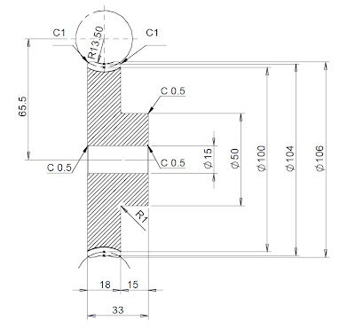
Thursday, December 4, 2008
How to Draw Mounting Boss in Solidworks?
 Create a variety of mounting bosses. Set the number of fins and choose a hole or a pin.
Friday, November 28, 2008
To Draw a Nut by Mechanical Desktop
 If you want to learn how to draw a nut by Mechanical Desktop (MD), here I give you a simple tutorial and I hope you can follow these steps by easy. Actually almost same the instruction of MD between the instruction of Solidworks, just a little different on the icon.
 * For better playback, allow the video to download before playing
 Download WMV ( 15.2MB compressed file )
Saturday, November 22, 2008
One Minute Tip - Extrude by Offset from Base Plane to "Up to Surface"
 You not necessary to create new base plane of the small hole base that have distance from base knob is 2.9mm. You just offset the sketch from base plane how depth that you want. And in "End Condition" you can extrude until "Up to Surface" by click inside peak of knob.
* For better playback, allow the video to download before playing
Download WMV ( 4.43MB compressed file )
You not necessary to create new base plane of the small hole base that have distance from base knob is 2.9mm. You just offset the sketch from base plane how depth that you want. And in "End Condition" you can extrude until "Up to Surface" by click inside peak of knob.
* For better playback, allow the video to download before playing
Download WMV ( 4.43MB compressed file )
Friday, November 21, 2008
To Draw Hexagonal Key by Swept Boss, Swept Surcafe & Text Cut Extrude
 In this tutorial, you can learn about Swept Surface, create Circular Pattern of Surface Sweep, Surface-Trim, Surface-Fill, and Surface-Knit. Please enjoy this tutorial
Wednesday, November 19, 2008
To Draw a Simple Ball Bearing
 Create sketch for inner and outer, then click revolved boss/boss. By the same methode, create the ball with 6.6mm of diameter. Then copy the ball by use circular pattern with amount of 12. Refer the bearing number to 16004 in catalog.
For better playback, allow the video to download before playing
Download WMV ( 7.55MB compressed file ) Monday, November 17, 2008
One-Minute Tip - Dimensions and Calculations
 From solidworks.com
Just about any calculation, simple or more advanced, can be achieved directly in SolidWorks
* For better playback, allow the video to download before playing
Download WMV ( 773KB compressed file )
From solidworks.com
Just about any calculation, simple or more advanced, can be achieved directly in SolidWorks
* For better playback, allow the video to download before playing
Download WMV ( 773KB compressed file )
Saturday, November 15, 2008
One Minute Tip - To Define of Mass Properties
 To define of the mass properties, in FeatureManager design tree right click on name of the part (exp.
  ) then select Appeareance and Edit Material. Under Material, please select the kind of material you want choise. Click OK.
On the Toolbar Menu, click Tool -- Mass Properties. So you can see the Mass properties of Worm Wheel.
* For better playback, allow the video to download before playing
Download WMV ( 1.12MB compressed file )
) then select Appeareance and Edit Material. Under Material, please select the kind of material you want choise. Click OK.
On the Toolbar Menu, click Tool -- Mass Properties. So you can see the Mass properties of Worm Wheel.
* For better playback, allow the video to download before playing
Download WMV ( 1.12MB compressed file )
Thursday, November 13, 2008
One Minute Tip - Sketch Blocks and Mechanisms
 From solidworks.com
Quickly simulate the motion and interaction of mechanisms using sketch blocks
* For better playback, allow the video to download before playing
Download WMV ( 1.2MB compressed file )
From solidworks.com
Quickly simulate the motion and interaction of mechanisms using sketch blocks
* For better playback, allow the video to download before playing
Download WMV ( 1.2MB compressed file )
Wednesday, November 12, 2008
One Minute Tip - Freeform - Adding a Deformed Surface
 From solidworks.com
Push and pull any 4-sided surface into the shape you want to create ergonomic shapes
* For better playback, allow the video to download before playing
Download WMV ( 1.7MB compressed file )
From solidworks.com
Push and pull any 4-sided surface into the shape you want to create ergonomic shapes
* For better playback, allow the video to download before playing
Download WMV ( 1.7MB compressed file )
Saturday, November 8, 2008
How to Stretch 3D Model by Deform in SolidWorks
 On 3D solid, you can stretch the model by use "DEFORM" ordered. First you create the Ellipse sketch at the base model, then select Insert > Feature > Deform. In FeatureManager Design Tree, select Initial Curve and Target Curve, so you can see about different.
Friday, November 7, 2008
To Draw a Bottle ( Part 4 - Finished )
 Ending of create the bottle, you will learn how to use surface, subtract, shell & combine of part. * For better playback, allow the video to download before playing Download WMV ( 10MB compressed file )
Please follow this link
To Draw a Bottle (Part 1)
To Draw a Bottle (Part 2)
To Draw a Bottle (Part 3)
Wednesday, September 17, 2008
To Draw Worm Wheel by Using Helix and Cut Sweep


Tuesday, September 16, 2008
To Draw a Worm Gear by Helix & Cut Sweep
 To draw worm gear, the ordered almost same like when you drew the Bolt and the Nut. With used helix and cut sweep to make the appearance of this teeth. You must determine this module before. To the explained you could see profile worm gear to the picture below:

Tuesday, September 9, 2008
To Draw a Bottle by Using Revolved Cut, Swept Boss & Combine - Part3

In this lesson you will learn how to extrude sketch of circle, how to create revolved cut, using swept boss/base with "twist along part" and without "merge result", how to mirror of cut extrude, and combine of 2 (two) solid bodies.
* For better playback, allow the video to download before playing
Download WMV ( 4MB compressed file )
Download WMV ( 4MB compressed file )
Friday, September 5, 2008
To Draw a Bottle by Using 3D Sketch, Lofted Boss & Dome - Part2
 In Part 2 of Bottle model, I add Lofted Boss in base of bottle with make new plane vertically down 2,9mm. For the new sketch, I offset base the contour of bottle to 1,5mm. After lofted boss was succeed, I make dome in base of bottle 2mm inside. For more detailed, I show you in video tutorial below. Good see.
* For better playback, allow the video to download before playing
In Part 2 of Bottle model, I add Lofted Boss in base of bottle with make new plane vertically down 2,9mm. For the new sketch, I offset base the contour of bottle to 1,5mm. After lofted boss was succeed, I make dome in base of bottle 2mm inside. For more detailed, I show you in video tutorial below. Good see.
* For better playback, allow the video to download before playing
 Download WMV ( 5.9MB compressed file )
Saturday, August 30, 2008
To Draw a Bottle by Using 3D Sketch & Lofted Boss - Part 1
 This model use 3D Sketch and Lofted Boss. You will learn how to draw by 3D sketch, convert line to construction line, lofted boss using profiles and guide lines, and others tips.
2. Click Rectangle  on the Sketch toolbar, and create a rectangle by the origin
  inside of rectangle.
3. Click Smart Dimension  on the Sketch toolbar, and create a rectangle by the origin
  inside of rectangle.
 (Dimensions/Relations toolbar), and fully defined the sketch.
 4. Click Offset Entities
  on the Sketch toolbar.
5. In the Property Manager, under Parameters:
on the Sketch toolbar.
5. In the Property Manager, under Parameters:- Set Offset Distance
 to 1.
to 1.

- Select Add dimensions, Reverse, and Select chain
 6. Select all entities in the graphics area by left click and drag a rectangular as shown below.
 7. In the Property Manager, under Option:
- Select For construction.
9. Click 3 Point Arc  on the Sketch toolbar.
10. On the one of inside entities, select start and end points, then drag the arc on the mid one of outside entities to set the radius.
 11. Click OK
12. Click Fillet
11. Click OK
12. Click Fillet  on the Sketch toolbar.
13. In the Property Manager, under Fillet Parameters:
on the Sketch toolbar.
13. In the Property Manager, under Fillet Parameters:
- Set Radius
 to 5.
to 5.

 14. Click OK , then Click Exit Sketch
  II. Creating 3D Sketch to Define Top and Side of Bottle
1. Click Isometric on
II. Creating 3D Sketch to Define Top and Side of Bottle
1. Click Isometric on  the Standard Views toolbar.
2. In the Feature Manager design tree, select the Top plane.
3. Click Plane
the Standard Views toolbar.
2. In the Feature Manager design tree, select the Top plane.
3. Click Plane  on the Sketch toolbar.
4. In the Property Manager, under First Reference:
on the Sketch toolbar.
4. In the Property Manager, under First Reference:
- Set Distance to 44.
.
6. Click Circle  on the Sketch toolbar.
7. Sketch a circle on Plane 2, with the center approximately along the same vertical axis as the sketch origin.
8. Click Add Relation  on the Dimensions/Relations toolbar.
9. In the graphics area select the arc and the origin
 10. In the PropertyManager, under Add Relations click Concentric
  , then click OK .
11. Click Smart Dimension on the Dimensions/Relations toolbar, and dimension the arc diameter to 21.
 III. Creating the First Splines
1. Click Plane on the Sketch toolbar.
2. In the FeatureManager design tree, select Front for First Reference.
3. In the PropertyManager, under First Reference:
III. Creating the First Splines
1. Click Plane on the Sketch toolbar.
2. In the FeatureManager design tree, select Front for First Reference.
3. In the PropertyManager, under First Reference:
- Click Coincident
 , then click OK
  .
.

 on the Sketch toolbar.
5. Sketch a two point spline coincident with the ends points of the tangent arc.
6. Repeat step 5 with the points shown.
on the Sketch toolbar.
5. Sketch a two point spline coincident with the ends points of the tangent arc.
6. Repeat step 5 with the points shown.
 7. Click Normal To
  on the Standard Views Toolbar.
8. Select one of the two entities on the graphic area.
9. Click the dot on head arrow and drag until became a curve.
on the Standard Views Toolbar.
8. Select one of the two entities on the graphic area.
9. Click the dot on head arrow and drag until became a curve.
 10. In the Property Manager, under Parameters:
- Set Tangent Weighting 1
 to 60.

- Set Tangent Radial Direction
 to -100.

 12. In the Property Manager, under Parameters:
- Set Tangent Weighting 1 to 60.
- Set Tangent Radial Direction to -80.
.
IV. Creating the Second Splines
1. Click Isometric on the Standard Views toolbar.
2. Click Plane on the Sketch toolbar.
3. In the FeatureManager design tree, select Right for First Reference.
4. In the PropertyManager, under First Reference:
- Click Coincident , then click OK .
on the Sketch toolbar.
6. Sketch a two point spline coincident with the ends points of the tangent arc.
7. Repeat step 6 with the points shown.
 8. Click Normal To on the Standard Views Toolbar.
9. Select one of the two entities on the graphic area.
10. Click the dot on head arrow and drag until became a curve.
8. Click Normal To on the Standard Views Toolbar.
9. Select one of the two entities on the graphic area.
10. Click the dot on head arrow and drag until became a curve.
 11. In the Property Manager, under Parameters:
- Set Tangent Weighting 1 to 55.
- Set Tangent Polar Direction
 to -10.

 13. In the Property Manager, under Parameters:
- Set Tangent Weighting 1 to 55.
- Set Tangent Polar Direction to -10.
, then Click Exit Sketch .
V. Creating Bottle by Lofted Boss
1. Click Isometric on the Standard Views toolbar.
2. Click Lofted Boss  on the Feature Toolbar.
3. Right-click in the graphics area and choose SelectionManager.
4. In the SelectionManager, click Select Closed Loop
on the Feature Toolbar.
3. Right-click in the graphics area and choose SelectionManager.
4. In the SelectionManager, click Select Closed Loop  .
5. Select the Sketch1 for Profiles
.
5. Select the Sketch1 for Profiles  and click .
 6. Select and accept the circular sketch for Profiles .
 7. In the PropertyManager, click in Guide Curves.
8. In the graphics area, right-click and choose SelectionManager. Use the Select Open Loop
7. In the PropertyManager, click in Guide Curves.
8. In the graphics area, right-click and choose SelectionManager. Use the Select Open Loop  tool to select the four splines for Guide Curves
  .
.
 9. Click OK .
10. Click Fillet
9. Click OK .
10. Click Fillet  on the Feature Toolbar.
11. In the Property Manager, under Item To Fillet:
on the Feature Toolbar.
11. In the Property Manager, under Item To Fillet:
- Set Radius to 1.5.
- Select Edge<1> of Loft in Edges, Faces, Features and Loops


 12. Click OK .
 Congratulations! You have completed this lesson.
For more detail, please see on video tutorial below:
* For better playback, allow the video to download before playing
Congratulations! You have completed this lesson.
For more detail, please see on video tutorial below:
* For better playback, allow the video to download before playing
 Download WMV ( 5.1 MB compressed file )
Subscribe to:
Posts (Atom)


