
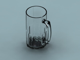
In this free tutorial I want to try to create drawing of a glass as shown in the image rendering as well as by using 3 main commands in SolidWorks program, namely:
first, revolved to form a glass tube;
second, circular pattern to create a motive glass bottom
third, loft to make the handle
After 3 steps, I tried rendering by changing the glass material on the command that is in material properties and the results are as shown in the picture you can see.
Let us begin the first step by creating a glass tube with a revolved command.
First; click the icon of revolved bose or insert > boss > revolve, then make a sketch on front plane then choose normal to so the results will appear in the image below 
For detailed sketch of the bottom you can see in the capture below

Make sure all the sketches in the condition of fully define marked with blue lines change color to be black. For a meeting between a straight line and radius relations using the add and select tangent. If all lines have been changed to black or fully define, click exit sketch.
On Feature Manager choose axis at origins. And the first step we have completed with results as shown below
Isometric View

Bottom View
Second; Create Contour
Choose icon cut extrude or insert > cut > extrude, then create sketch at right plane. Follow the steps making sketches like the image below

After that click Exit Skecth, then on Feature Manager set Direction1 and Direction2 at up to next

 Then click OK
 Third; Loft, to make a handle.
At the Loft command, which need to be prepared is to sketch the contours of the handle and guide curve from ear top to bottom like the letter c reversed. This time I'll make her guide curve first. First I will make this handle and my first half to make to the two planes, in the middle and 8mm offset from the center as the thickness of this grip. For the plane in the middle, click on the Feature Manager plane fronts and create a sketch as shown in the picture below

For more details, I show the top and bottom

 Bottom View

When finished, click Exit Sketches. And now you have to have two plane sketches, each of which has two guide curve.
The next step is to create a sketch profile handles. There are three profile that we will create, first at the top and then in the middle and the third at the bottom. For the top and bottom, we use the right plane in his sketch, and then using a top plane to sketch the contours of the center. To be continued ....


