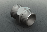
 Already long time I did not write the tutorial. Hopefully I can forward more often to write a tutorial with examples of 3D models are simple and often encountered. Previously I apologize to you, that the continuation of large glass drawing yet I continued in this tutorial. Hopefully in a short time I will write the sequel.
 In this tutorial, I will create a "union thread." This model is usually used for joints between pipes. The main command is Extrude Boss and Cut Sweep. Coupled with the supporting command and Chamfer Cut Extrude.
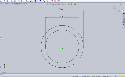
Dimensional model which I will make is a pipe with outside diameter of 33mm and internal diameter of 26mm. First we make a first sketch for the pipe model that we place on the right plane.
In the Feature Manager plane right click and select Insert> Feature Boss / Base> Extrude. Now we are ready to make sketches for pipe model. Select Tools> Sketch Entities> Circle. Create two circles centered at the origin with a dimension of 33mm and 26mm respectively. Then click Exit sketch.
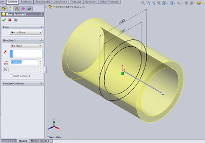
After Exit Sketch and Feature dialog box is displayed Manager. Fill out the number 52 on the column depth and select Mid Plane in direction 1.
Next we will give chamfer at both ends of the outer pipe. Select Insert> Features> Chamfer. In the Feature manager selection ends of the pipe that will be chamfer. Then specify the distance Chamfer you want. In this tutorial, enter the number 1.5 and angle of 45 °. Then click OK.
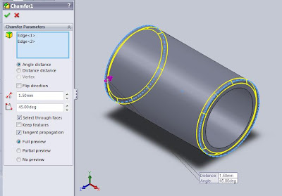
The next step which is the core of this model is to create a path treaded on the surface of the pipe. It is actually we have mentioned in the tutorial "How to Draw a Bolt." But that's okay, we will repeat this command in this tutorial. Just you know, the program SolidWorks is so nice when you have many creations in the making of images of 3D models. Views are so smooth you can enjoy on your computer screen. The model that we will create is always displayed in another color which of course will help you to imagine the image will be created.
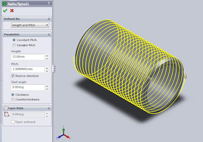
Back to the topic. To create a plot thread, you first create a "path" or grooves that will be passed by the sketches. On the menu select Insert> Curve> Helix / Spiral. Determine the plane on the outside of the pipe to make a sketch of the circle. Make a sketch of a circle with a diameter of the outer pipe that is 33mm, then click OK. Then in the dialog box select the type of Height and Pitch. Fill in height with 52 and Pitch 2.3, and then click Reverse to change the direction of his path and fill the Start Angle to 0 °. Then click OK.
After that, you will create a sketch profile. Because of its Start Angle has been determined at the 0 ° which is located on the Top Plane, then click on the Top Plane Feature Manager and select Tools> Sketch entities> Polygon. Then a dialog box will appear. Under the parameters, the contents of the Number of Sides with the number 6 and then click and drag the cursor to make a triangle. After that edit the sketches that you create by adding a box on it (but this is only option) and its width should not exceed the dimensions of its pitch.
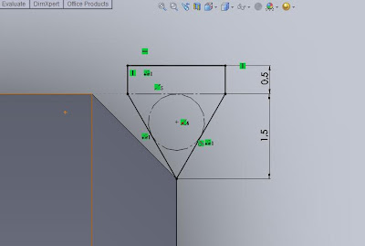
To facilitate this exercise, I enter his tread depth of 1.5mm and an additional box height 0.5mm. You also can enter the appropriate numbers in accordance with existing standards.
Once the path and the profile is established, the next step is melkukan cutting process. Profile sketches as a form of cuts and path as the cutting grooves. On the menu select Insert> Cut> Sweep. Then a dialog box that asks for the specified path and profile sketches. Under Profile and Path dialog box, you just enter the required profile and its path. Then click OK.
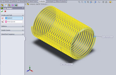
Up here will look that the entire surface of the pipe will have a plot thread. To make the middle, there is no plot thread, so I try to use the technique with a closed surface with Base Extrude command. This technique will make the model look better.
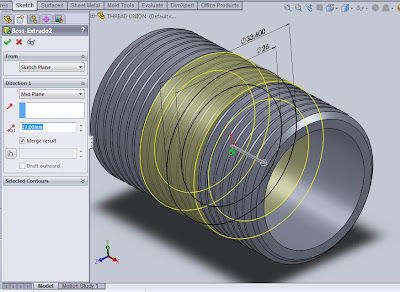
In the Feature Manager Plane Right-click and select the menu Insert> Boss / Base> Extrude. Make a sketch of a circle by selecting Tools> Sketch Entities> Circle and create two circles, each with diameter of 26mm and 33.6mm. Click OK.
In the dialog box under the Directions a select Mid Plane and fill with a depth of 17mm. Check the Merge result. Then click OK. Illustration like the picture below.
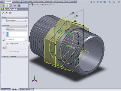
The next stage is to create a hexagon that is located right in the middle of the model. In the Feature Manager Plane Right-click and select Insert> Boss / Base> Extrude. Create a sketch polygons by selecting the command Tools> Sketch Entities> Polygon. Then create a 26mm diameter circle also sketch by selecting the command Tools> Sketch Entities> Circle. Then click OK.
Then a dialog box appears as shown below and fill in the Mid Plane to Direction 1 with a distance of 12mm, check the Merge result then click OK.
A step we will solve the model "Threaded Union", namely by adding a chamfer on both sides of the hexagon extrusi. On the menu select Insert> Cut> Extrude, and define the plane on one side of the outer hexagon and click. Click the circle in the hexagon section and select the command Tools> Sketch Tools> Convert Entities, and then click OK. Dialog box appears. Under the Direction a select Through All, 60 ° Draft Angle write and check Flip side to cut. Click OK.
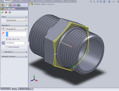
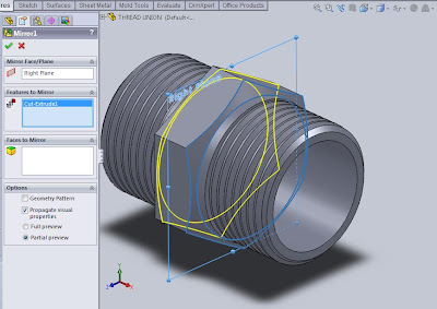
Finally, copy the Extrude command to cut the cut the next side of the Mirror command. In the Feature Manager Plane Right-click and select Insert> Pattern / Mirror> Mirror. In the dialog box under the Feature to mirror select Cut-Extrude you just created and click OK.
