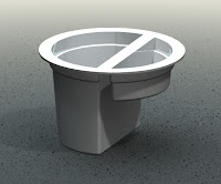
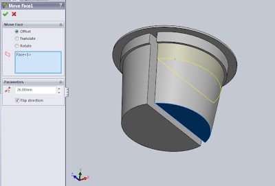
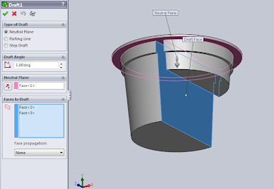
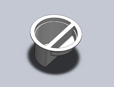
Dipper of water that I often wear when bathing is very interesting for model made its 3D image. There are two parts that can be aggregated before we start drawing, the water container and the handle. Although simple but it never hurts for us to try to create an image model. Dipper model that you encounter may be different than what I got. But one thing is not different is the top cross-sectional area larger than the bottom section. There is no intention other than to facilitate the model problem also print or injection process.
Immediately, we begin to draw
On the menu select File, New. Part and then click OK.
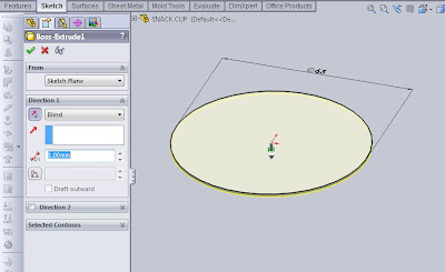
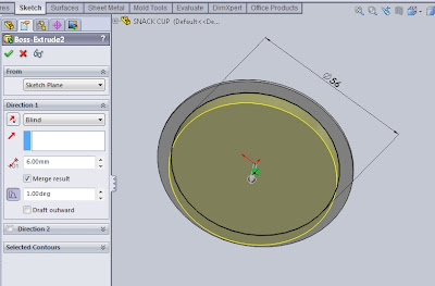
On Feature toolbar or select Insert Extruded Boss, Featured, Extruded Boss/Base. Then determine its plane by selecting the top plane. Make a sketch of a circle with a diameter of 150mm (we could write a diameter of 150 in the dialog box or we can also use smart sketch dimension on the menu). Click Exit the sketch. Then in the dialog box below Direction1 select End Condition: Blind to the direction of the arrow upwards. Set Depth to 100mm, angle of 2 degrees, the check draft outward. Then click OK.
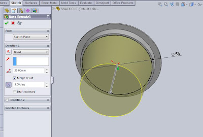
Then with the same command, select the Extrude Boss. Then place the cursor on the upper surface of the Extrude Boss that we just created to determine the location of his plane. Click the upper-outer edge of the Extrude Boss was then select Convert Entities on the Sketch menu. Then we will have a sketch of a circle that has been "fully define sketch" whose characteristics we can see that the circle is black instead of blue, without having to make a sketch first and enter the circle diameter value. Then in the dialog box below Direction1 select End Condition: Blind to the direction of the arrow upwards. Set Depth to 40mm, angle 10 degrees, check draft outward. Then click OK.
Next we add the radius of 7mm at the bottom outer edge of the image above. On Feature toolbar or select Insert Fillet, Feature, Fillet.
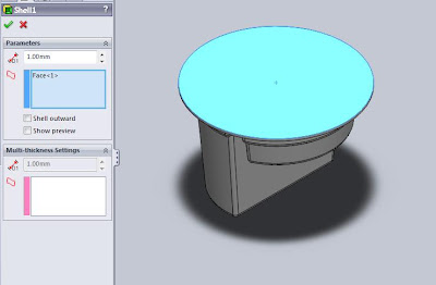
Thick dipper on this model I created with a thickness of 2mm. To make it from a solid to above select command shell on the toolbar or Insert Feature, Feature, Shell. Click the surface in which you want holes are marked in blue. Check the preview show to see the picture of the results we will get later. Click OK.
Thick dipper on this model I created with a thickness of 2mm. To make it from a solid to above select command shell on the toolbar or Insert Feature, Feature, Shell. Click the surface in which you want holes are marked in blue. Check the preview show to see the picture of the results we will get later. Click OK.
Rotate the image to see the profile of the bottom by clicking the scroll, hold, then move the mouse until the bottom looks. This time we will add the rib at the base of dipper that serves as an amplifier as well as foot bailer. On the toolbar select the Extrude Feature and click on the bottom surface so that changes color to blue, which is as his plane. Click on the circle line the bottom and select Convert Entities on the Sketch toolbar. OK and Exit Sketch.
Then in the dialog box below Direction1 select End Condition: Blind to the direction of the arrow down. Set Depth with 1mm and check the Merge result. Click the Thin Feature, select One-Direction and set 2mm thick downward direction. Click OK.
Then in the dialog box below Direction1 select End Condition: Blind to the direction of the arrow down. Set Depth with 1mm and check the Merge result. Click the Thin Feature, select One-Direction and set 2mm thick downward direction. Click OK.
Finally, the process of making a container of water in the first part is completed we make. Next we create an image that is the second part of the handle. This time I want to show you a tip offset distance in accordance with a sketch of what we want to utilize the existing origin plane as a planar base without having to create a new planar again. Click on Front Plane Feature Manager and select Extrude on the toolbar or select Insert Feature, Feature, Extrude.
Click Normal To on the Menu toolbar or press "Ctrl F8". On the Sketch toolbar select the Rectangular and create a sketch of a square as shown in the figure below.
Click OK and then Exit Sketch.
In the dialog box below Extrude3 Boss From the parameters, select the offset and set the distance at 250mm. Under Direction1 select parameters and click Next Up To reverse direction to determine the position of the handle. Click OK.
Next add the fillets on the outer side of the handle 15mm and 50mm at the bottom of the handle that attaches to the container, by selecting the Fillet command on the toolbar or Insert Feature, Feature, Fillet.
Make a handle with a thickness of 2mm thick wall thickness equal to the water container. Shell commands can be returned to use. The surface of the blue that we eliminate.
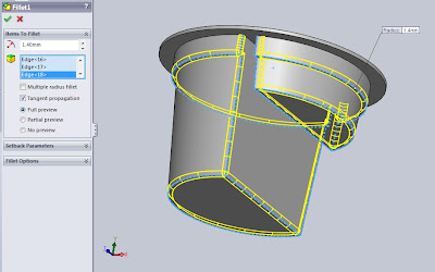
Then add the radius on the upper side of the container and the outside of the top of the handle with a radius of 2 mm. Choose the fillets on the toolbar feature. Under the parameters set Item To Fillet radius with 2mm and selection ends a radius added. Click OK.
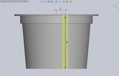
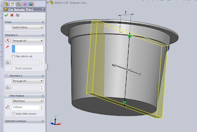
Next we will add a hole for the hanger we make dipper which was situated at the tip of the handle. On the toolbar select Extruded Cut Feature, and then place it on the planar surface of the handle. Create a sketch from the Sketch toolbar Straight Slot. Determine the dimensions as shown in the picture below. Click OK and Exit Sketch. Then, under Direction 1, set Depth to 5mm. Click OK.
Add rib reinforcement around the hole with a width of 2mm and 1mm thick. On the toolbar select Extruded Boss Feature and click on the surface to be added reinforcement rib. Selection of one end. Then on the Sketch toolbar select Convert Entities to make a line sketch. Further selection of all other edges and then click OK. Exit Sketch.
Under the Direction 1, set Depth to 1mm, then check the Thin Feature. Set with 2mm thickness. Click OK. And now we've had a rib reinforcements.
Add a radius of 1 degree at each end of the inner and the outer end of the rib. On the toolbar select Fillet Feature and click on the surface of Extruded earlier results which will automatically select all the outer and inner edge. Set the radius to 1mm. Click OK.
For more details, please see the video tutorial below which I have previously uploaded to Youtube.


